
PET-MRI principle
PET-MRI is a hyphenated imaging technique using Magnetic Resonance Imaging, MRI, combined to a Positron Emission Tomography, PET. This nuclear imaging spectrometer is used in medicine to monitor molecular activity of an organ. The PET-MRI principle and equipment is presented in the following article: What is PET-MRI? and, RS2D preclinical imaging systems are presented here.
PET-MRI principle
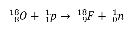
To detect the cellular activity, the tracer is injected, and the patient is introduced in the PET ring. Then, the radioactive isotopes (tracers) are emitting positron (or β+ particles) according to the following processes, let’s take the Fluor as an example. The isotope is generated in a cyclotron thanks to an irradiation of oxygen by a proton [1]:
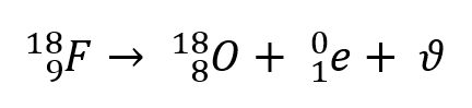
Then, the 18F is disintegrated into 18O with an emission of a particle, named positron (or antielectron):
![]()
and a neutrino:
![]()
into
The emitted positron will then annihilate with an electron of the patient and generate the emission of two high energy gamma photons which travels in diametrically opposite direction. See figure 3:
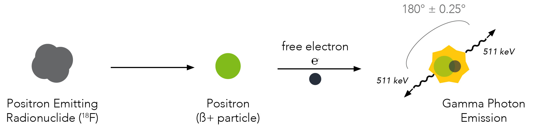
Figure 3: Positron emission and annihilation reaction
Each photon has an energy of 511 keV. Two detectors at opposite ends facing each other detect these two photons traveling in opposite directions, and the radioactivity is localized somewhere along a line between the two detectors. This is referred to as the line of response (LOR). See figure 4.
The detection ring is composed of a scintillating crystal (also called gamma camera) and photosensors. Crystals interact with the 511keV gamma photons. It should be small and have several properties (high atomic density, high linear damping factor, high light output) to ensure a high spatial resolution. The most used crystal are the Sodium Iodide (NaI), the Bismuth Germanate Oxide (BGO), Yttrium Orthosilicate (YSO), Lutetium-Yttrium Oxyorthosilicate (LYSO) and Lutetium Oxyorthosilicate (LSO).
When a gamma-ray strikes the crystal, photons of visible light are produced at a rate proportional to the energy of the gamma-ray. The light produced is detected by the photosensor located behind the crystal. The photosensor convert the light to an electrical signal, its an electronical collimation (in comparison to the SPECT technique).
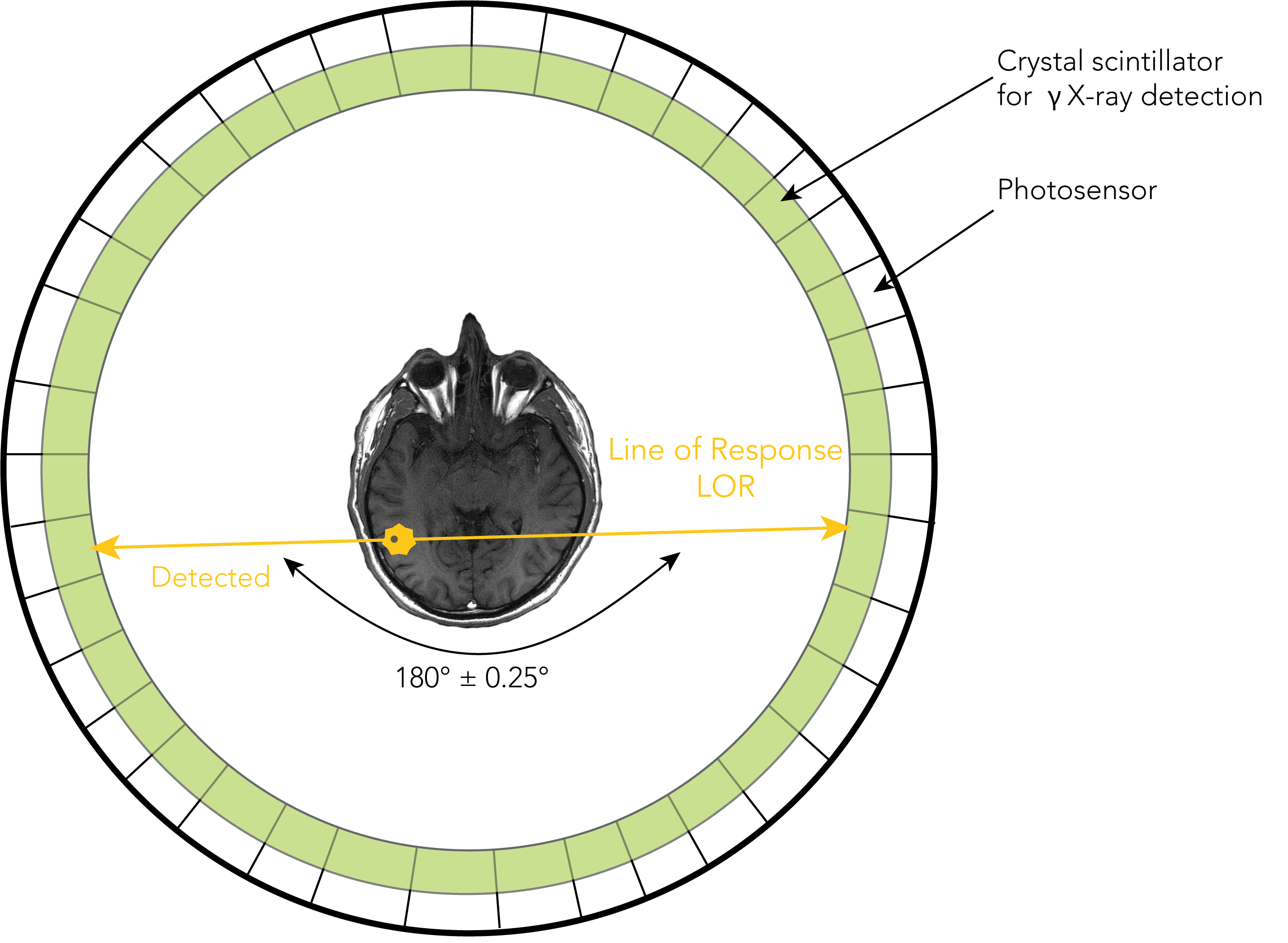
Figure 4: Signal detection in a PET ring showing collimators
Along the LOR, one can measure a response line on which the annihilation took place, although without knowing its precise position. The emission probability is uniform along the LOR.
It is possible to measure additional parameters of the positron decay with coincidence detection by using detectors with extremely good time resolution. A very accurate measurement of the time difference between the interactions occurring in the two detectors allows the use of temporal information to locate the event. This technique is called time-of-flight (TOF) PET. The time difference (Δt), between the arrival times of the two coincidence photons, can be related to the location of the annihilation (Δx), relative to the midpoint between the two detectors according to the following equation:
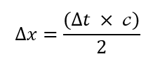
With c the speed of light.
The TOF allows to decrease statistical noise dispersion in the post processed image by reduction of the random coincidence. Yet, what is a random coincidence [2]?
The types of events detected by a PET can be categorized in three groups: True (signal), Scatter (background) and Random (background).
True coincidence are types of coincidences detected allowing useful and correct information to locate the annihilation along the LOR connecting two detectors.
Two photons coming from the annihilation of two different positrons can be detected simultaneously. This coincidence is called random (or fortuitous). This is unfavorable since it does not come from a unique event, although it is counted as such. The location of the annihilation will be erroneous, hence the importance of reducing the width of the coincidence window as much as possible.
Scatter coincidence occurs when two annihilation photons undergo a Compton diffusion scatter interaction before reaching the detector (they are scattered by the electrons of the matter).
See figure 5.
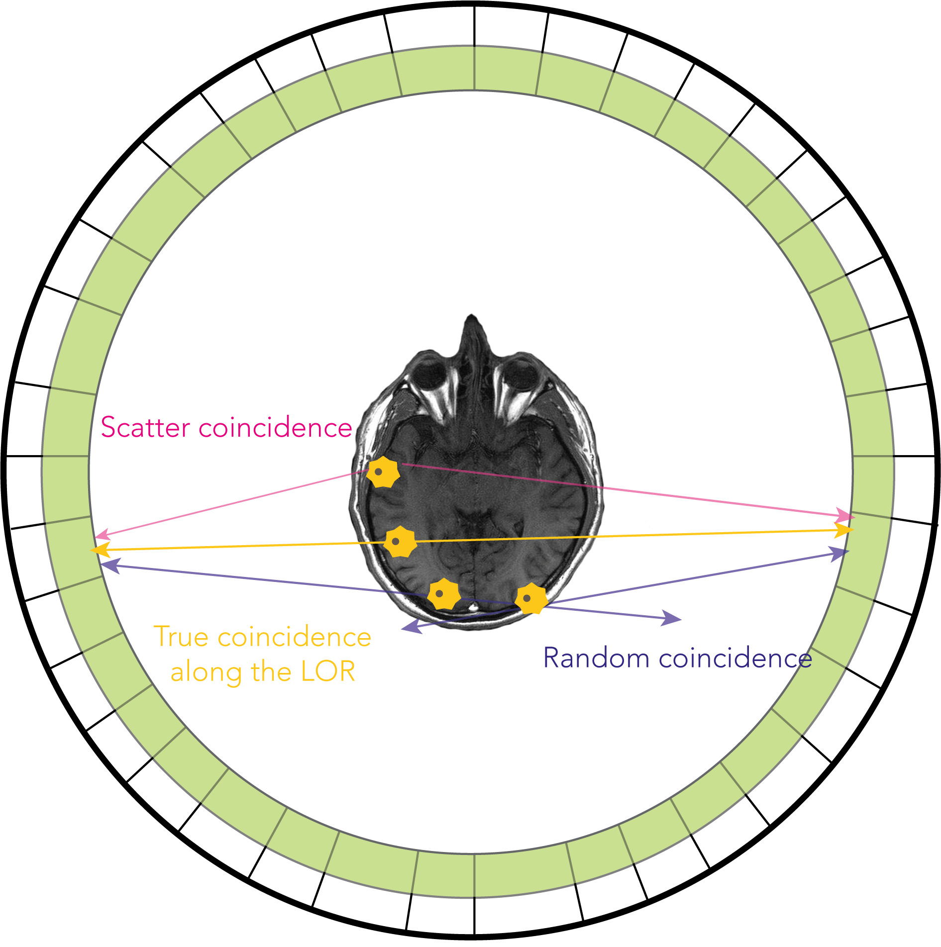
Figure 5: Coincidence events in PET imaging shown on a single detector ring
The random to true count rate ratio of coincidence can be reduced by using faster detectors or absorptive septa to restrict the sampled region containing the activity.
You would like to know more details about PET, PET-MRI or preclinical imaging systems, contact us anytime you need.
You wish to know more about NMR or MRI ? Stay tuned on our twitter to read new articles soon.
Bibliography
[1] The physics of PET/CT scanners, Ruth E. Schmitz, Adam M. Alessio, and Paul E. Kinahan
[2] Seminars in Nuclear Medicine, Vol XXXIV, No 2 (April), 2004: pp 87-111